Fasteners
Even today, most aircraft (both metallic and composite) are assembled using some type of fastener. There were attempts to not use fasteners, but to my knowledge this has not been successfully accomplished. Therefore, they seem to stay to preferred way to assemble aircraft.
There are many types of fasteners available, but the most common used in aircraft assembly are:
- Solid rivets
- Blind rivets
- Screws
- Bolts
Fastener analysis
When a fastener analysis is being done, there are two things that need to be checked. They are:
- Fastener strength (shear, tension and bending)
- Bearing strength in the connected parts
Fastener or joint analysis?
Since the joint check covers both the fastener strength (shear, tension and bending) and the bearing strength, a more appropriate name is the joint analysis, and this name is preferred by the engineering community.
Allowable
It is also important to mention that the joint allowable are readily available and they are usually based on tests. When calculating the Margin of Safety these values are used.
Fastener sizing
When picking the fastener diameter, special attention should be taken. The following are some rules of thumb.
- A very strong fastener should not be installed in a thin sheet. If this is done the sheet will be the weak link.
- A small fastener should not be installed in thick parts, as it may be undersized for the application and lack sufficient strength.
- Minimum fastener diameter:
drivet = 3*tthinnest_sheet
For 0.050 in. thick aircraft aluminum sheet, 5/32 in. rivet should be used (1/8 or 3/16 could also be used).
- No rivets should be installed in assemblies with a total material thickness greater than 1/4 in. (0.25 in.). However, experience has shown that assemblies with a total thickness exceeding 1/8 in. are generally not well suited for riveted joints. For thicker assemblies, Hi-Lite®, Hi-Lok®, screws, or bolts are more appropriate fastening options.
Joints rules of thumb
- The joint should be designed to be bearing-critical rather than shear-critical.
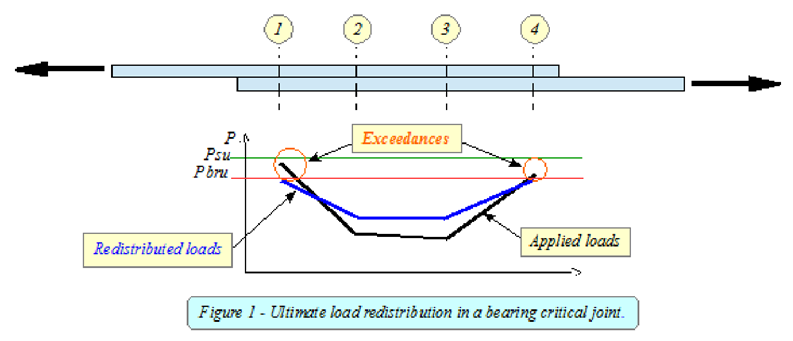
Bearing-critical joint:
When a multiple-fastener joint is bearing-critical (MSbearing < MSshear), the total ultimate load is redistributed more evenly among the fastener group due to local bearing deformation.
This behavior can be understood by considering a simple splice and the way load is redistributed among the fasteners. Fastener 1 is the most critical because it initially carries the highest load. Once the load reaches a level that causes slight yielding of the hole, the fastener stiffness (thus the load) decreases, and the load it can carry is effectively capped at its ultimate bearing allowable. As a result, the adjacent fastener (Fastener 2) begins to carry an increasing share of the load. This redistribution process continues progressively until the load is distributed evenly among all fasteners, with each carrying its maximum ultimate bearing allowable (Pbru). Only after all the fasteners have reached their ultimate bearing allowable that the joint will fail.
NOTE: This is only applicable at the ultimate load. At the limit load, the peaking effect must be considered, as no yielding is allowed.
Shear-critical joint:
In a shear-critical joint, the load in the most critical fastener 1 will keep increasing until the fastener reaches its shear allowable (Psu) and then it will then fail. After this happens, the total load from fastener 1 will be moved to the adjacent fastener 2 and it will be simply added to the existing load of fastener 2. After the fastener 2 fails, the total load of fastener 2 (load of already failed fastener 1+load of fastener 2) will be added to the fastener 3. This is called the “Zipper” effect. It happens very fast and it is catastrophic. As a result of that, it is not recommended for single load path critical joints.
NOTE: In general, even if a joint is shear-critical, the assumption of distributing the total applied ultimate load evenly across the rivets is usually recognized and accepted.

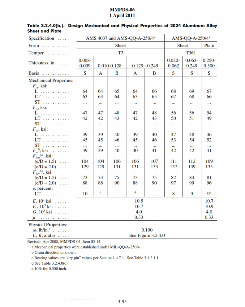
- At limit load, the peaking at the end-fasteners should not exceed the yield bearing allowable (Pbry) and the yield shear allowable (Psy).
Disadvantage of using Hi-Loks
- Using Hi-Loks in every joint would be expensive, as they cost significantly more.
Advantage of using Hi-Loks
- Shear allowable is higher (solid rivet 5/32 has 595 lbf, and Hi-Lock has 2005 lbf)
Conclusion
- Always use joint allowable when available when calculating the fastener Margin of Safety
- When the joint allowable is not available, calculate the fastener MS based on the weakest allowable between shear and bearing.
- Design a bearing-critical joint in critical single load path locations (ex. in the case of extremely high and short flight maneuver loading condition, the peak load would be “absorbed” by the bearing critical joint without hopefully causing any damage.
- Rivets have been around for a long time, and they are still one of the best ways to connect two aircraft parts together.
- Advantages:
- Removal and replacement of a damaged part is quickly, using minimal tools.
- Disadvantages:
- Need to drill holes in otherwise perfectly smooth components. These holes are one of the major causes of crack initiation in the connected parts.
- Advantages: